Design of a modular DMX Transceiver
Introduction
This shows the abstract design of a modular DMX Transceiver. The goal is to have a design that can then be implemented as VHDL or Verilog in an FPGA or Custom Chip or can be implemented complete or in parts in software e.g. in a realtime processor.
Overview of the Design
On the left you will find a DMA Controller that connects to the DMX/RDM transceiver on the right.
The DMA controller is the bridge between the frame memory interface and the dmx transceiver.
![[dmx port overview]](dmx_port_overview.svg)
The interface between the DMA controller and the DMX transceiver is symmetric, that means that it is
possible to connect one dmx transceiver to another. This is shown in the next diagram.
This diagram implements a store and forward unit for dmx frames. The frames can be transferend in both directions.
The two sides can then be seen as two collision domains in a network. You can put a filter inbetween the two,
for example to filter out specific frames. All RDM frames could be filtered out.
![[dmx port bridge]](dmx_port_bridge.svg)
The signal txstart_i, that goes into the transmitter parts is always true. This is due to the fact that a transmision is started,
as soon as data is available on the transmitter and txstart_i is true.
DMX Transceiver implementation details
The following diagram shows the details of the dmx transceiver implementation. It splits up into three parts.
In the upper path you find the DMX transmitter, in the lower part the DMX receiver and inbetween sits the RDM controller.
![[dmx port implementation]](dmx_port_details.svg)
The transmitter and the receiver can also be used on its own.
The Transmitter
The Transmitter splits up into five components. These are the frame-decoder, the transmitter-controller, a pulse generator for the break, a fifo and the serializer. The frame-decoder acts as the incoming interface. It received the byte stream, decodes it, sends the dmx payload to the fifo and the control data to the transmit-controller. The transmit-controller acts as the main state-machine of the transmitter and coordinates all activities. It initiates the generation of the break signal and controls the fifo and the serializer. The fifo acts as a clock domain barrier for the dmx-payload. The serializer does the serialization of the parallel data into the 8N2 format used for dmx512.
The Receiver
Comming soon...
The RDM Controller
Comming soon...
Breadboarding Setup
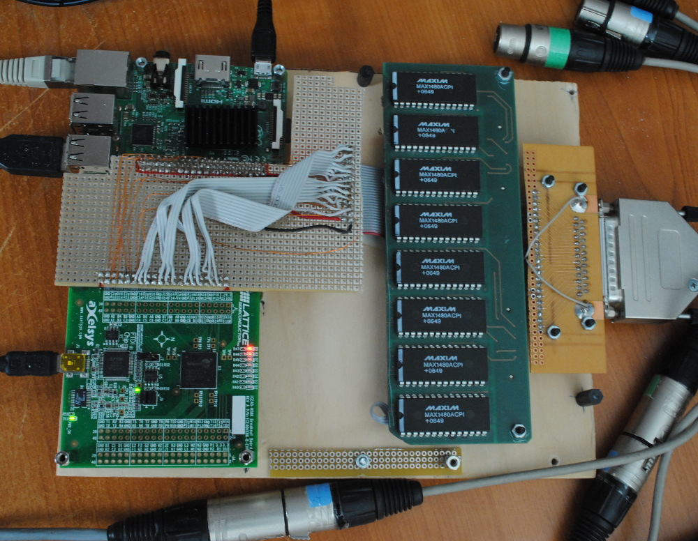
The following image shows a first setup with a RaspberryPI2, an iCE40HX-8K Breakout Board, an old 8-port RS485 level shifter board.